🛴 Arduino Digital Speedometer for Razor A5 Lux Kick Scooter AKA Zvezdalet
Transform your kid’s Razor A5 Lux Kick Scooter into a high-tech ride with this Arduino-based digital speedometer! This project combines a classic analog speedometer display with colorful LED strip effects that respond to your speed in real-time.
🚀 Features
- Dual Display Modes: Switch between classic analog speedometer and LED light show
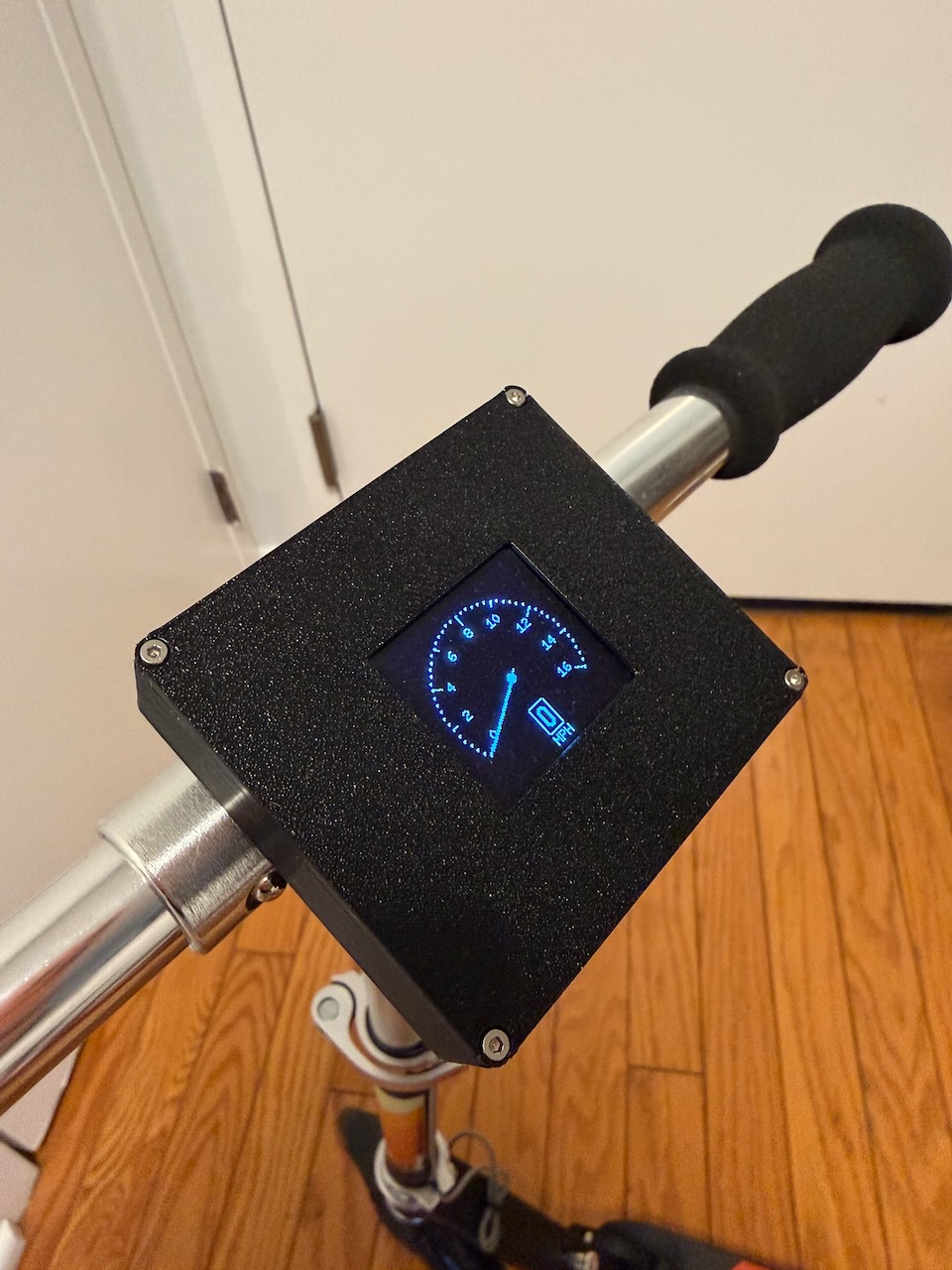
- Real-time Speed Tracking: Hall effect sensor provides accurate speed measurement up to 16 MPH
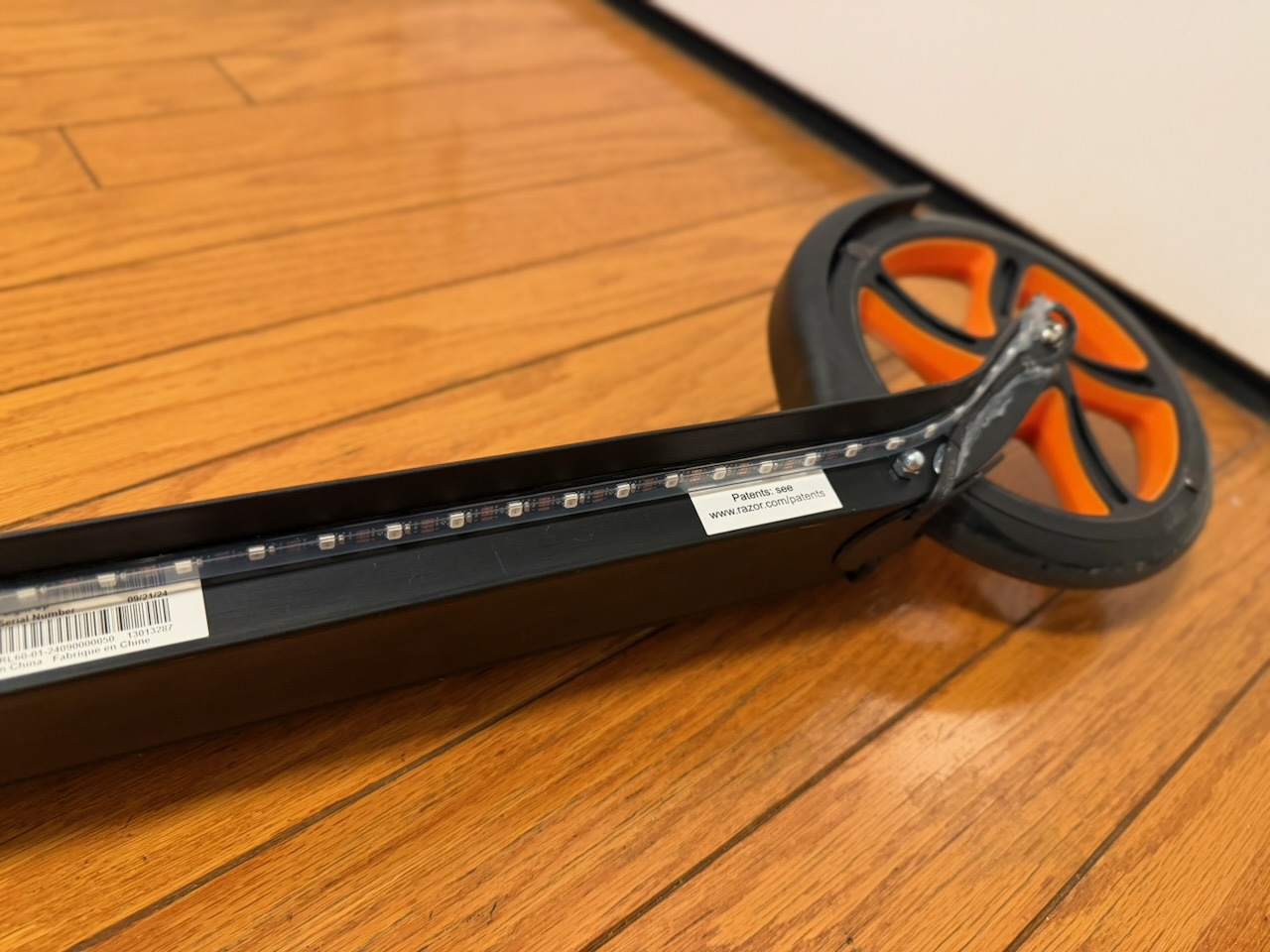
- Color-coded LED Strip: 60 RGB LEDs change color based on speed (blue for slow, red for fast)
- Running Light Effects: Dynamic “comet tail” LED animations during ride
- Rechargeable: Built-in LiPo battery with charging circuit
- Weatherproof Design: 3D printed enclosure protects electronics
- Easy Assembly: Modular design with clear wiring diagram
📋 Components List
Electronics
- Adafruit ItsyBitsy 32u4 - 3V 8MHz - Main microcontroller - Link
- Waveshare 1.5inch OLED Display Module - 128x128 grayscale display - Link
- Adafruit Mini Skinny NeoPixel Digital RGB LED Strip 1m - Black 60 LED - Link
- Adafruit LiIon/LiPoly Backpack Add-On for Pro Trinket/ItsyBitsy - Battery charging circuit - Link
- Lithium Ion Polymer Battery - 3.7v 2500mAh - Link
- Hall Effect Sensor - US5881LUA - Speed detection - Link
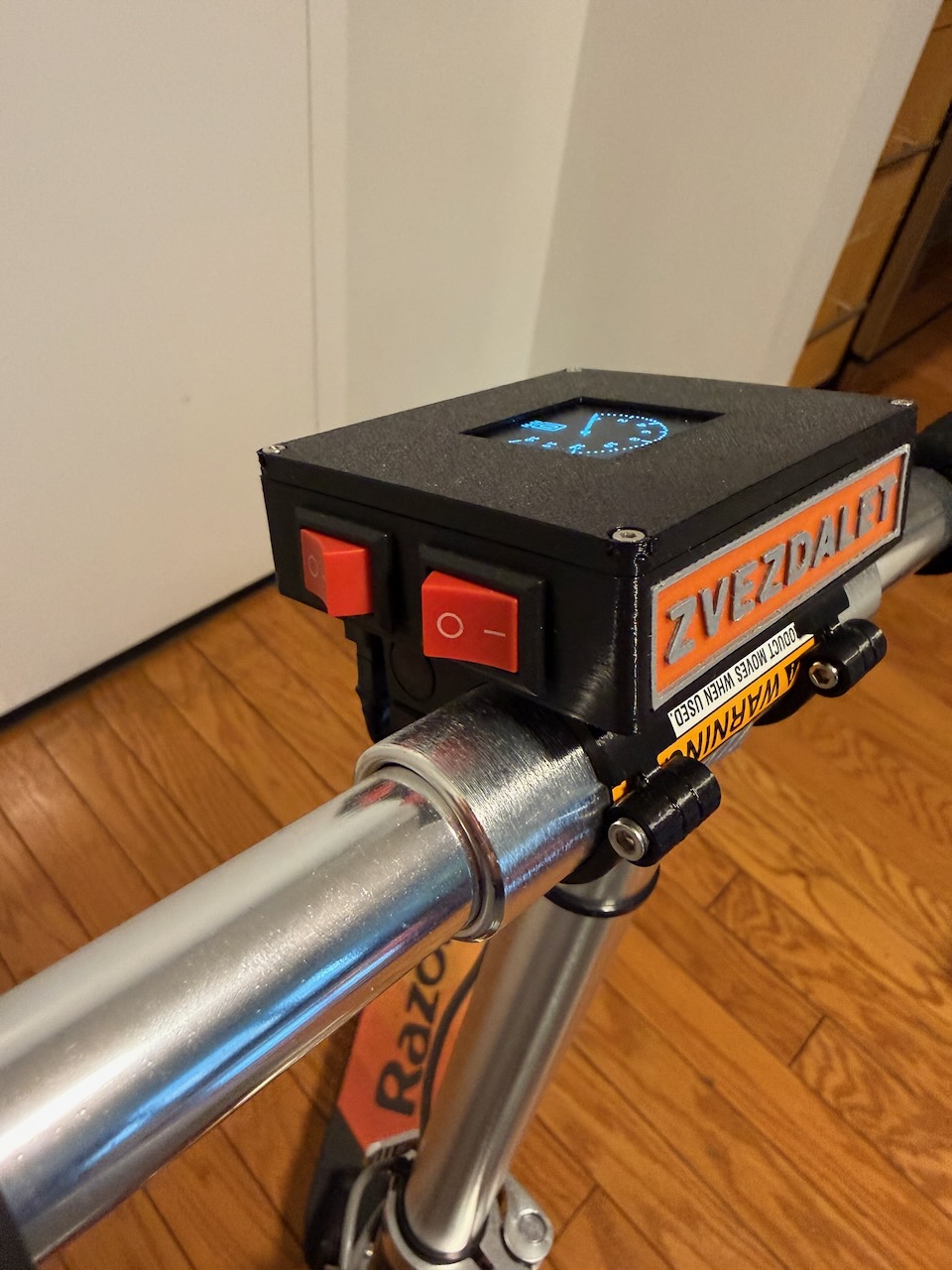
- Mini Rocker Switch On Off - Power and mode switching - Link
Hardware
- M2 Screws - Assembly hardware - Link
- JST Connectors - Modular connections - Link
- 4 Conductor Shielded Wire - Sensor wiring - Link
- 3M Double Sided Tape - Mounting - Link
Compatible Scooter
- Razor A5 Lux Kick Scooter - Link
🖨️ 3D Printed Parts
Print the following STL files:
box.stl- Main enclosure for battery, switches, and JST connectorbox_battery_holder.stl- Battery compartment with ItsyBitsy mountingbox_logo.stl- Two-color decorative logo platelid.stl- Top cover with OLED display mountconnector_bottom.stl- Lower clamp for scooter attachmentconnector_top.stl- Upper clamp (connects with M3 bolt)connector_lock.stl- Locking mechanism (secured with M2 bolt)
Print Settings
- Layer Height: 0.2mm
- Infill: 20%
- Support: Yes (for overhangs)
- Material: PLA or PETG recommended
⚡ Wiring Diagram
.png)
Follow the provided wiring schematic carefully:
- Hall Sensor: Connect to interrupt pin 2 for speed detection
- OLED Display: SPI connection (CS=10, DC=7, RESET=8)
- NeoPixel Strip: Data pin 5, power through battery backpack
- Switches: Power switch and mode toggle (pin 12)
- Battery: Connected through LiPoly backpack for safe charging
🔧 Assembly Instructions
- Print all STL files using recommended settings
- Install electronics in battery holder:
- Mount ItsyBitsy to battery holder with hot glue
- Connect LiPoly backpack underneath
- Install battery with double-sided tape
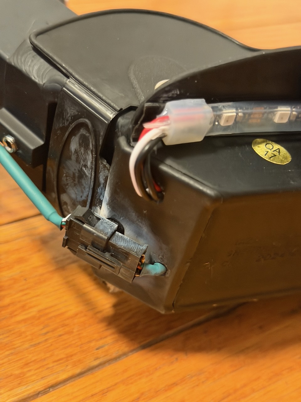
- Prepare main box:
- Install rocker switches in designated slots
- Mount JST connector for external connections
- Connect wiring according to schematic
- Install OLED display in lid
- Attach to scooter using connector system:
- Position connector_bottom on scooter pole
- Secure with connector_top using M3 bolt
- Insert connector_lock with M2 bolt for security
💻 Firmware
The Arduino code provides:
- Speed calculation from hall sensor pulses
- Dual display modes (speedometer/LED show)
- Color mapping based on speed
- Safety limits (16 MPH maximum display)
- Auto-timeout (speed resets to 0 after 3 seconds)
Upload the provided oled_speedometer.ino to your ItsyBitsy using Arduino IDE.
Required Libraries
- U8g2lib (for OLED display)
- Adafruit_NeoPixel (for LED strip)
🎯 How It Works
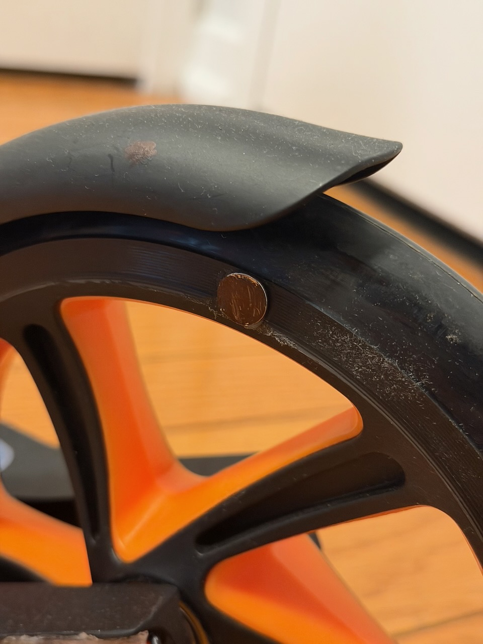
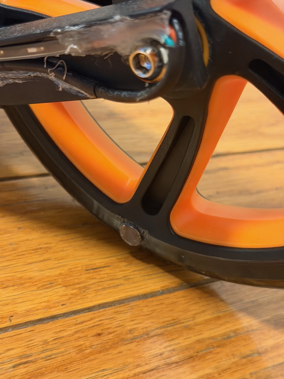
- Speed Detection: Hall sensor detects magnets on the wheel (2 magnets recommended)
- Calculation: Arduino calculates speed using wheel circumference (798mm for 10” wheel)
- Display: Shows analog speedometer on OLED with digital MPH readout
- LED Effects: Switch to LED mode for colorful running lights that change with speed
⚙️ Customization
- Wheel Size: Adjust
WHEEL_CIRCUMFERENCE_MMin code for different wheels - Magnet Count: Modify
MAGNETS_PER_REVOLUTIONbased on your setup - Speed Limit: Change
MAX_SPEEDfor different ranges - LED Count: Adjust
LED_COUNTif using different strip length
🔋 Battery Life
With the 2500mAh battery:
- OLED mode: ~8-10 hours continuous use
- LED mode: ~4-6 hours (LEDs consume more power)
- Standby: Several days with power switch off
🛡️ Safety Notes
- Always wear appropriate safety gear when riding
- Speed readings are for fun - always ride at safe speeds
- Check local laws regarding scooter modifications
- Ensure all connections are secure before riding
- Adult supervision recommended for installation
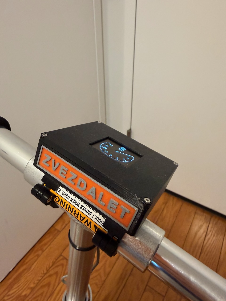
📸 Gallery
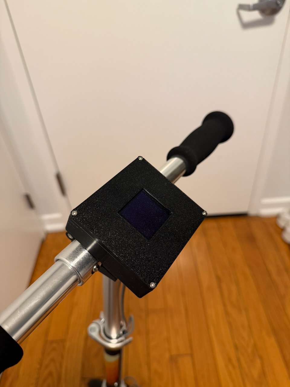
🎉 Results
This speedometer adds an exciting tech element to any kick scooter ride! Kids love watching their speed and the LED effects, while parents appreciate the safe speed monitoring. The modular design makes it easy to remove for charging or storage.
Perfect project for:
- STEM education
- Arduino beginners
- Kids who love tech gadgets
- Anyone wanting to upgrade their scooter
Follow this link https://www.printables.com/model/1440259-arduino-digital-speedometer-for-razor-a5-lux-kick to get STL files.
📄 License
This project is open source - feel free to modify and improve! Share your variations and improvements with the community.
- Difficulty: ⭐⭐⭐☆☆ Intermediate
- Time: 4-6 hours assembly + printing time
- Age: 12+ (with adult supervision)
Happy riding! 🛴⚡